


 |
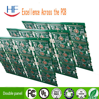
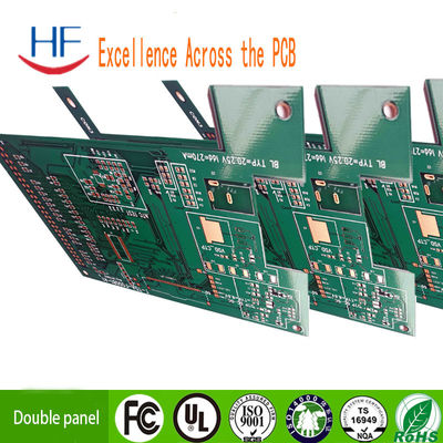
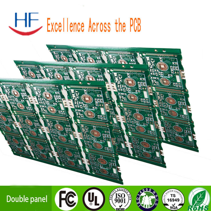
5V 1.2A LED PCB Board Prototype Circuit Board For Power Bank
Product Details:
| Place of Origin: | China |
| Brand Name: | HF |
| Certification: | ISO CE |
| Model Number: | design PCB |
Payment & Shipping Terms:
| Minimum Order Quantity: | 5PCS |
|---|---|
| Price: | Negotiable |
| Packaging Details: | High quality carton packing, high quality vacuum packing, |
| Delivery Time: | 5~8 days |
| Payment Terms: | L/C, T/T,PAYPAL |
| Supply Ability: | Ten thousand square meters per month |
|
Detail Information |
|||
| Model: | K6-PCBA | Input: | 5V1.2A |
|---|---|---|---|
| Output: | 5V1A, 5V1.2A | Battery Voltage Range: | 3.7V±0.5V |
| Capacity Display Range: | 1%-100% | Support Capacity Range: | 450,000 UA |
| Main Board Three-dimensional Size: | 65*22*15MM | Color: | Green |
| High Light: | 1.2A LED PCB Board,5V LED PCB Board,1.2A Prototype Circuit Board |
||
Product Description
ISO9001 Power Bank 5V 1.2A LED PCB Board Prototype Circuit Board
Capability
| High precision prototype | PCB bulk production | ||
| Max Layers | 2 layers | 1-14 layers | |
| MIN Line width(mil) | 4mil | 4mil | |
| MIN Line space(mil) | 4mil | 4mil | |
| Min via (mechanical drilling) | Board thickness≤1.2mm | 0.35mm | 0.2mm |
| Board thickness≤2.5mm | 0.35mm | 0.3mm | |
| Board thickness>2.5mm | Aspect Ration≤13:1 | Aspect Ration≤13:1 | |
| Aspect Ration | Aspect Ration≤13:1 | Aspect Ration≤13:1 | |
| Board thickness | MAX | 6mm | 5mm |
| MIN | 2 layers:0.2mm; | 2 layers:0.2mm | |
| MAX Board size | 620*1100mm | 620*1100mm | |
| Max copper thickness | 2 oz | 2 oz | |
| Immersion Gold/ Gold Plated Thickness |
Immersion Gold:Au,1—8u” | ||
| Hole copper thick | 25um 1mil | 25um 1mil | |
| Tolerance | Board thickness | Board thickness≤1.0mm:+/-0.1mm 1.0mm<Board |
Board thickness≤1.0mm:+/-0.1mm 1.0mm<Board thickness≤2.0mm:+/-10% Board thickness>2.0mm:+/-8% |
| Outline Tolerance | ≤100mm:+/-0.1mm 100< ≤300mm:+/-0.15mm |
>300mm:+/-0.2mm | |
| Impedance | ±10% | ±10% | |
| MIN Solder mask bridge | 0.05mm | 0.10mm | |
| Plugging vias capability | 0.05mm | 0.70mm--1.00mm | |
Features:
Adopt advanced digital audio signal processing (DSP) technology
And FM modulation phase-locked loop (PLL) to make the sound more realistic,
More stable performance, long working time, no frequency deviation
LCD display is more intuitive and accurate, with extremely low power consumption and minimal noise interference
Built-in 16-bit digital volume adjustment button operation can be easily completed
All data will not be lost after 100 years of power failure before the automatic power failure
Multi-channel audio input automatic switching
When returning to light (with backlight button operation, no automatic button operation
Turn off the backlight for 20 seconds, depending on the camera problem, the LCD visual effect is better than the actual photo.
Application: FM wireless audio, USB PC audio broadcast, wireless microphone, maternal and child care
specification:
Output power: 100mW
Audio response: 50Hz-18KHz
Transmission frequency: 87.0MHz-108.0MHz
Modulation mode: standard FM radio
Channel: LINE / USB channel (stereo), MIC channel (mono)
Equivalent noise:> 30dB (sound is close to CD quality)
Power supply voltage: DC 3.0 V-5.0V
Working current: 35mA
Transmitting antenna: 75cm telescopic antenna
Transmission distance: 75 cm standard whip antenna connection, radio Tecsun PL-660, measuring 100 meters of open land.
Size: approx. 26.5x49mm / 1.04"x 1.93"
Instructions for use:
<1>: Power
The module corresponds to the port-, +, and then the negative and positive terminals of the power supply (battery). It is recommended to use batteries or other power sources for power supply. You cannot use a switching power supply without a filter (such as a low-quality switching power supply such as a mobile phone charger), otherwise the power generated by interference will affect the normal operation of the module. The normal working voltage of this module is 3.0-5.0V, be careful not to exceed the power supply voltage range
<2>: Button
Volume +/-: press volume +/- 1, + /-press continuously
Frequency +/-: Press frequency +/- 0.1MHZ, long press continuously +/- 1MHZ
Mute: press this button to switch mute/unmute
<3>:
Antenna ANT port used to connect FM antenna for better transmission of FM signals. It is recommended that an external whip antenna with a length of 75cm is not obstructed when approaching the antenna
<4>: USB audio connection
If you need the USB audio broadcasting function of this module, you need to connect the USB cable to the computer. The USB port is compatible with ordinary mobile phones. You can use a USB cable to connect the mobile phone and the computer module. Due to the computer's USB 5V output, you can directly connect the computer to the USB port, and the USB powers the module. After connecting the computer USB, this module will automatically enter the PC audio playback mode, the LCD screen will display the PC, the computer will automatically install the driver end, and name this module "CD002" sound card device, set the built-in computer voice-enabled to enable "CD002" Audio equipment, the computer system through this module audio, FM transmission mode,
<5>: LINE audio connection
If you need the LINE (line input) channel of this module as the source transmitter, just plug the audio cable into this module, 3.5mm audio jack, and plug the other end into the audio device (such as mobile phone earphone) hole), and the module will automatically switch to LINE channel FM transmitter as source. Just adjust to the consistency of the nearby FM radio transmission frequency and the module, you can hear the audio from the side of the phone
<6>: FM wireless microphone
If you need this module as a source to transmit MIC, LINE only needs to unplug the line and USB cable (that is, there is no LINE and USB connection), and the module will automatically use the MIC FM channel as the transmitting source. This module has a very high-sensitivity microphone on the body. The wireless microphone can be used as needed and kept by mothers and babies. Please note that when using this module transmitter to adjust the volume with the best pickup effect
![]()
![]()
![]()
Applications:
Communications
Traditional telecommunication equipment, FTTP, VOIP, multimedia services, data networking and IT infrastructure products, wireless infrastructure products, power amplifiers, splitters and combiners, high power transistors, etc.
Computer Peripherals
High end printers, cable modem, wireless routers, IP telephones, consumer and office products, banking system etc.
Consumer
Computers, televisions, cameras, digital video recorders (DVR), handheld products, LED, etc.
Automotive
Passenger safety systems, engine control systems, air bags, traction control products, etc.
High End Computing and Storage
High performance computer and server, mainframe system and storage equipment, memory, etc.
Industry
Power supply, main control panel, monitor, CCTV products,automotive control equipment, industry robot, access control products etc
Medical
Magnetic resonance imaging (MRI), computed tomography (CT), emergency response defibrillation units, patient monitoring, implantable devices, robotic surgery systems, biometrics and diagnostic equipment, etc.
![]()